Industrial Flanges & Hammer Unions
Industrial flanges to ASME/ANSI B16.5 and hammer unions (Hammer Union) for high-pressure drilling lines and oil and gas operations.
Category Overview
Tose'e Tejarat Sayyalat supplies two main families in this category: industrial flanges to ASME/ANSI B16.5 for joining pipework, valves and process equipment, and hammer unions for the mobile high-pressure lines used in oil and gas operations.
In refineries, petrochemical plants and oil and gas pipelines, flanges are the most common demountable joint between two sections of pipe, valves, pumps or process equipment. Unlike a welded joint, a flange allows equipment to be inspected, repaired or replaced without cutting the line open. A hammer union, by contrast, is designed for mobile, temporary high-pressure lines — cementing, acidising and well control lines in drilling operations — that must be made up and broken out quickly without bolted tooling. It seals metal-to-metal and is tightened by striking the lugs with a hammer.
Industry reference — flange pressure classes to ASME B16.5
ASME B16.5 classifies industrial flanges into dimensionless pressure classes. The actual permissible pressure for each class depends on the flange material and the operating temperature. The table below gives the approximate permissible pressure of each class at ambient temperature for Group 1.1 carbon steel (such as ASTM A105).
| Pressure class | Approximate permissible pressure at ambient temperature |
|---|---|
| Class 150 | Approx. 285 psi (19.6 bar) |
| Class 300 | Approx. 740 psi (51 bar) |
| Class 600 | Approx. 1,480 psi (102 bar) |
| Class 900 | Approx. 2,220 psi (153 bar) |
| Class 1500 | Approx. 3,705 psi (255 bar) |
| Class 2500 | Approx. 6,170 psi (425 bar) |
The flanges we supply are available as slip-on, weld neck, blind, socket weld and threaded types, in sizes from NPS 1/2" to 24".
Industry reference — hammer union figure classification
Hammer unions are classified to API 6A by a figure number, each of which defines the geometry of the union and its pressure rating. The table below lists the figures most commonly used in the oil and gas industry.
| Figure | Cold working pressure (CWP) | Typical application |
|---|---|---|
| Fig 100 / 200 | Up to 1,000 psi (69 bar) | Low-pressure fluid lines |
| Fig 206 | Up to 15,000 psi (1,034 bar) | Standard and sour service lines |
| Fig 602 | Up to 6,000 psi (414 bar) | Cementing and acidising lines |
| Fig 1002 | Up to 10,000 psi (690 bar) | High-pressure cementing and well stimulation lines |
| Fig 1502 | Up to 15,000–20,000 psi (1,034–1,379 bar) | Ultra-high-pressure cementing, fracturing and well control lines |
| Fig 2002 | Up to 20,000 psi (1,379 bar) | Ultra-high-pressure well stimulation lines |
- Sealing: Metal-to-metal, with no O-ring needed on most models.
- Make-up and break-out: By striking the wing nut lugs with a hammer, with no bolted tooling required.
- Interchangeability: Unions made to API 6A are interchangeable with equivalent products from other established international manufacturers.
Selection by application
Each of these products has its own page with the full technical specification.
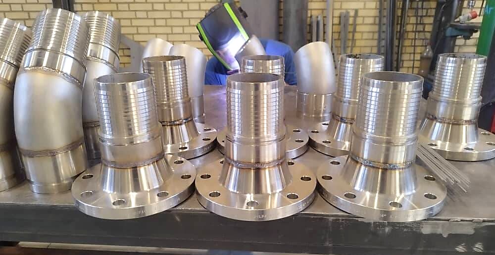
Industrial flange
Slip-on, weld neck, blind, socket weld and threaded flanges in Class 150 to 2500 for pipework and process equipment.
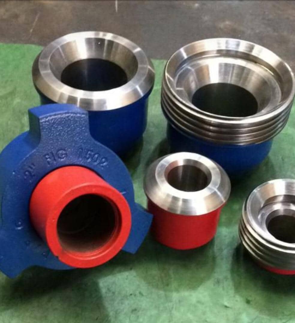
Hammer Union
High-pressure quick connection with a metal-to-metal seal, for mobile cementing, acidising and well control lines.
Technical Catalogue
The technical catalogue for industrial flanges and hammer unions is available on request from our sales department.
Request the technical catalogueRequest a Quotation
This website is not an online shop and enquiries are not registered automatically through the site. The fastest route is to send your specification on WhatsApp, or contact us directly on the numbers below.
Send us the size, standard and pressure class you require by phone, WhatsApp or email.